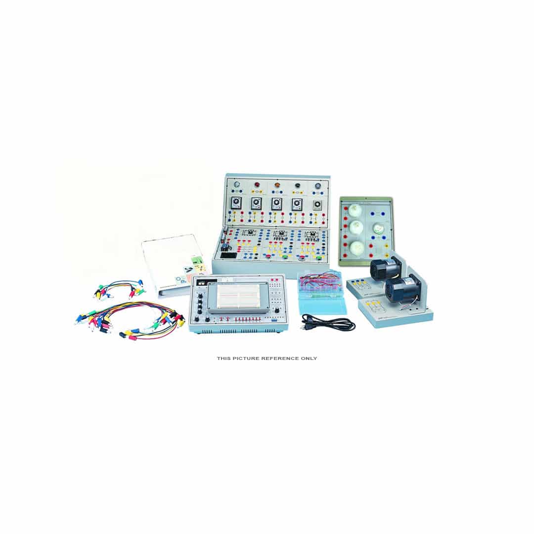
Description
BASIC ELECTRONICS TRAINER MODEL:
DC POWER SUPPLY
(1) Fixed DC power supply:
a. Voltage range: +-5V+-12V
b. Max. Current output: 0.3A
c. With output over-load protection
(2) Dual DC power supply:
a. Voltage range+-3V to +/-18V, continuously
adjustable.
b. Max. Current output: 1A
c. With output over-load protection
AC POWER SUPPLY
a. Voltage range: 9V to 0V , 9V
b. Max. Current output: 500 m A
c.With output over-load protection
SINGAL GENERATOR
(1) Pulse generator: (TTL level)
a. Frequency range: 1Hz to10KHz 4
settings, continuously adjustable
b. Fan out: 10 TTL load
(2) Pulse switches:
Pulse switches:
a. 2 independent output, TTL level
b.With Q, Q output,pulse width gerter5ms.
c. Fan out: 10 TTL load
(3) Data switches
a. 8 sets independent control output,TTL level with De-bounce circuit.
b. Fan out: 10 TTL load
FUNCTION GENERATOR OF BASIC ELECTRONICS TRAINER
(1)Output waveform: Sine, triangle, square.
(2) Output frequency: 10 to100KHz/4 settings, continuously adjustable
(3) Output amplitude: 18Vpp (open circuit) 9Vpp (50 O load)
TESTING AND DISPLAY
(1) 3 1 div2 digital voltmeter/ammeter
a. DC voltage range: 2V 200V
b. DC voltage accuracy: +/-(0. percentage of reading +1 digit)
c. DC current range: 200
Galvanometer
a. Current range 50mA.
b. Accuracy Class 2.5
LED indicator
a. 10 sets independent LED indicates high,
low logic state .
b. Input impedance: ≥100KΩ
Digital display
a. 2 sets independent 7-segment LED
b. With BCD-7segment decoder/driver and
DP Input.
c. Input with 8-4-2-1 code
Breadboard:
1680 tie-point breadboard on top panel can be easily put into and taken off.
Accessories Of Basic Electronic Trainer: Experiment manual, connection leads, connection plugs, breadboard.
List of Module:
a. Basic Device Module
b. Basic Electricity Experiment Module
c. Sensor Module(1)
d. Sensor Module(2)
e. Diode, Clipper and Clamper Module
f. Rectifier, Differentiator Integrator Circuit Module.
g. Transistor Amplifier Circuit Module
h. Multi-Stage Amplifier Circuit Module
i. FET Circuit Experiment Module
j. OP Amplifier Circuit Module 1, 2, 3, 4, 5.
k. Combination Logic Circuit Experiment Module 1, 2, 3, 4, 5.
l. Sequential Logic Circuit Experiment Module 1, 2
j. System Transformer ( stae delta )
List of Experiment:
Basic Measurement:
Resistance Measurements
Potentiometer characteristics
DC Voltage measurement
DC current Measurement
Ohm’s law application
AC voltage measurement
AC current measurement DC Circuits
Series-parallel network and kirchhoff’s law
Wheatstone bridge
Superposition, thevenin’s and norton’stheorems
Power in DC circuit
Maximum power transfer theorem
DC RC circuit and transient phenomena
DC RL circuit and transient phenomena AC Circuits
AC RC circuit – AC RL circuit .
AC RLC circuit
Series-resonant circuit
Parallel-resonant circuit
Power in AC circuit
Control Circuits
Water Level Control
Metal Detector
Light Controller Diode Characteristics
PN-junction diode Characteristics
Zener diode Characteristics
LED Characteristics
Photodiode Characteristics
Rectifiers and Filters
Half-wave rectifier
Full-wave rectifier-Bridge rectifier
Dual-power rectifier
Voltage doubler Diode Clipping and
Clamping Circuits
Clipping circuits
Clampping circuits Differentiator and Integrator
RC circuit
Differentiator circuit
Integrator circuit
RL circuit Transistor Characteristics
Basic transistor Characteristics
Transistor Characteristics curves Multistage Amplifiers
RC-coupled
D i r e c t – c o u p l e d a m p l i f i e r – T r a n s i s tor-coupled amplifier
Dual-end push-pull amplifier
FET Characteristics
JFET Characteristic s
MOSFET Characteristic
FET Amplifiers
JFET CS amplifier
JFET CD amplifier
MOSFET CS amplifier
OPA AMP Characteristics
differential amplifier in OP AMP
OP AMP Characteristics measurements
Basic OP AMP Circuits
Inverting amplifier
Non inverting amplifier.
Voltage follower.
Differential amplifier.
Adder Clipping circuit.
Constant voltage circuit
Constant current circuit.
Differentiator
Integrator
Instrumentation amplifier.
OP AMP Applications
Active high-pass filter.
Active low-pass filter
Active band-pass filter
Tone control circuit
OP AMP Comparators and Oscillators
Comparators
Schmitt trigger
Window comparator,
Monostable multivibrator.
Astable multivibrator.
Sine wave oscillator.
Crystal oscillator
Logic gate circuit
TTL circuit
CMOS circuit Threshold voltage measurement
Measuring TTL threshold voltage.
Measuring CMOS threshold voltage.
Voltage/current measurement
Measuring TTL I/O voltage and current.
Measuring CMOS voltage and current.
Characteristics of basic logic gates
Measuring AND gate characteristics.
Measuring OR gate characteristics
Measuring NOT gate characteristics.
Measuring NAND gate characteristics.
Measuring NOR gate characteristics
Measuring XOR gate characteristics
Interface between logic gates
TTL to CMOS interface.
CMOS to TTL interface.
Combinational Logic Circuits
NOR gate circuit
NAND gate circuit
XOR gate circuit
Constructing XOR gate with NAND gates
Constructing XOR gate with Basic gates.
AOI gate circuits Comparator circuits
Constructing comparator with basic logic gates
Constructing comparator with TTL IC
Adders and Subtractors
Half-and Full-Adder Circuits
Constructing half- and full-adders with
basic logic gates
Constructing 4-bit full-adder with IC – Constructing BCD adder.
Half-and Full-Subtractor Circuits
Constructing half-/full-subtractors with basic logic gates
Constructing 4-bit full-subtractor with IC Encoders and Decoders
Encoder circuits
Constructing 4-to-2-line encoder with basic gates.
Constructing 10-to-4-line encoder with
TTL IC – Decoder circuits – Constructing Decoder circuits
Constructing 2-to-4-line decoder with basic gates
Constructing 4-to-10-line decoder with TTL IC
Constructing BCD-to-7-segment decoder5.
Multiplexers and Demultiplexers
Multiplexer circuits Constructing 2-to-1-line multiplexer with basic gates
Using multiplexer to create function.
Constructing 8-to-1-line multiplexer with TTLIC Demultiplexer circuits
Constructing 1-to-2-line demultiplexer with basic logic
Constructing 1-to-8-line demultiplexer with CMOS IC
Analog Multiplexer/demultiplexer circuits Arithmetic Elements
Arithmetic Logic Unit (ALU) circuit Parity generator circuit
Parity generator constructed with XOR gates.
Parity generator IC Sequential Logic Circuits Flip-flops
Constructing RS flip-flop with basic logic gates
Constructing D flip-flop with RS flip-flop
Constructing JK flip-flop with RS flip-flop
Constructing master-slave JK flip-flop with RS flip-flop
Constructing shift register with D flip-flops
Preset left/right shift register Constructing noise elimination circuit with RS flip-flops
Counters- Constructing divide-by-8 counter with JK flip-flops
Constructing synchronous counter with JK flip-flops
Constructing divide-by-8 counter with 7490
Constructing BCD Counter with 7490.
Sequential Logic Applications -Moving LED control
Traffic light control


